UV Map Generator
![]()
Brief Description
Generate a UV Map using a motion-vector pass analysis and then applies it to the source image.
Description
Similarly to the UV Map modifier, this modifier applies a UV-Map to an image in order to match-move the motion of a source video. The UV-Map is generated as a first pass analysis.
The correct setup to match-move an image with the UV Map generator is to have your match-move logo on top of a layer with the original footage.
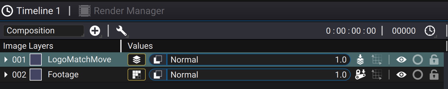
If your logo is a Composition, make sure to check Adjust To Source Format so that the internal transforms of the logo Composition are not concatenated with the UV map generator.
Once the UV Map generator is created as a modifier of the Source of the logo layer, it still needs to know where to find the footage to compute the motion vectors from. You must reference it from the Motion Source parameter
Computing the UV Maps
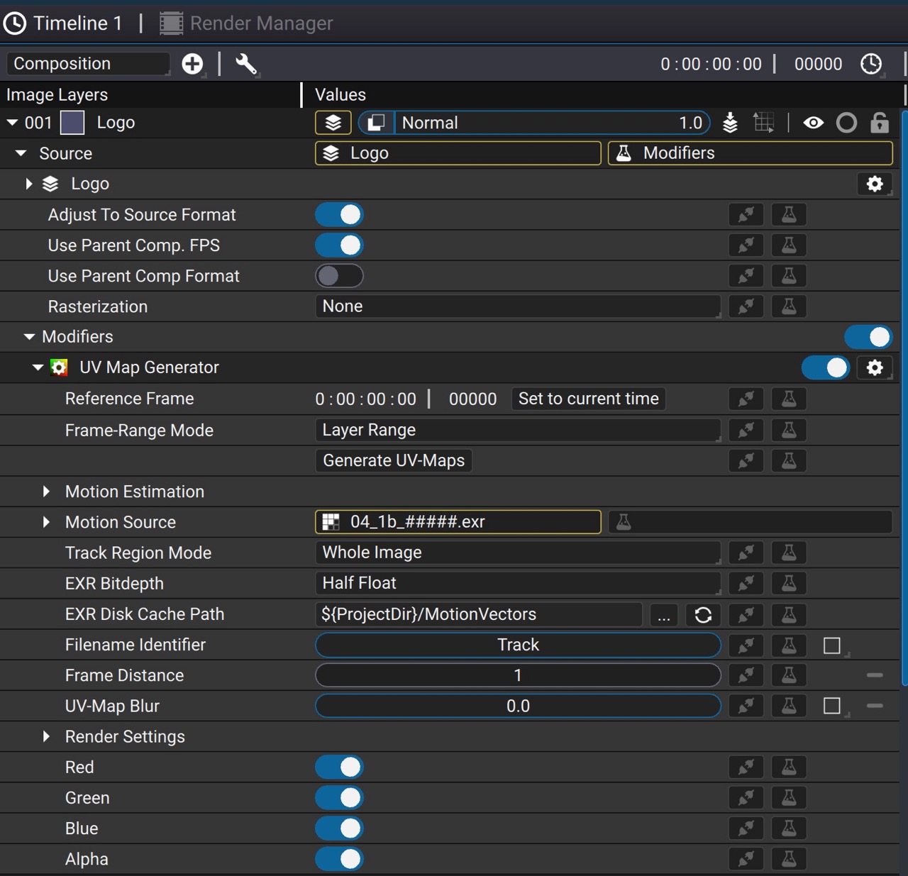
Before anything can be match-moved, we need to first compute the motion vectors from the source video. A few parameters control the generation process itself:
-
Reference Frame: This is the frame where the generated UV Map will be identity, that is, the logo will be unchanged at this frame. This should be set to the frame where you can best draw/fit the image you want to match-move.
-
Frame-Range Mode: Whether to generate UVMaps for the full range of the layer or just the specified frame-range
-
Motion Estimation: A set of parameters used to control the motion estimation algorithm. These are expert settings and the default values are reasonably well set
-
Track Region Mode: If set to Whole Image, the motion vectors and UV Maps will have the same size as the source footage. To speed things up, if the area you want to match-move is a much smaller region in the image, you can set a Track Region and use the rectangle widget in the viewport to define the region to compute. Note that in this mode, you should take care of adding extra padding so that motion vectors are clearly coherent thoughout the sequence, otherwise artefacts will appear at the edge of the track region
-
EXR Disk Cache Path: The directory where to write the motion-vectors and UV Maps.
-
Filename Identifier: This identifier is added in the filename of the generated files so that it may be easier for you to identify them
-
Frame Distance: This parameter indicate the frame-step at which to compute the motion vectors. The default value of 1 will compute the motion vectors between each consecutive frame. Increasing this value will compute the motion vectors every N frames, which will result in a much smoother motion, but may introduce drift. A higher value is useful for very slow motion over a long period of time.
The default value of EXR Cache Disk Cache Path uses the ${ProjectDir} variable to reference the location of your project directory. Thus make sure your project is saved, otherwise it will not be able to write the EXRs on disk.
Once parameters are set, click on the Generator UV-Maps button. For each frame, Autograph will write forward and backward motion-vectors in a multi-channel EXR and the UV-Map in a separate EXR image.
Placing the image to match-move
To place the image to match-move on the orignal footage, make sure your timeline is set at the frame as the Reference frame parameter. If you need to use a Transform or Corner Pin to place your image, make sure to use a Composition to encapsulate the image to match move and have the transformation in the Composition.
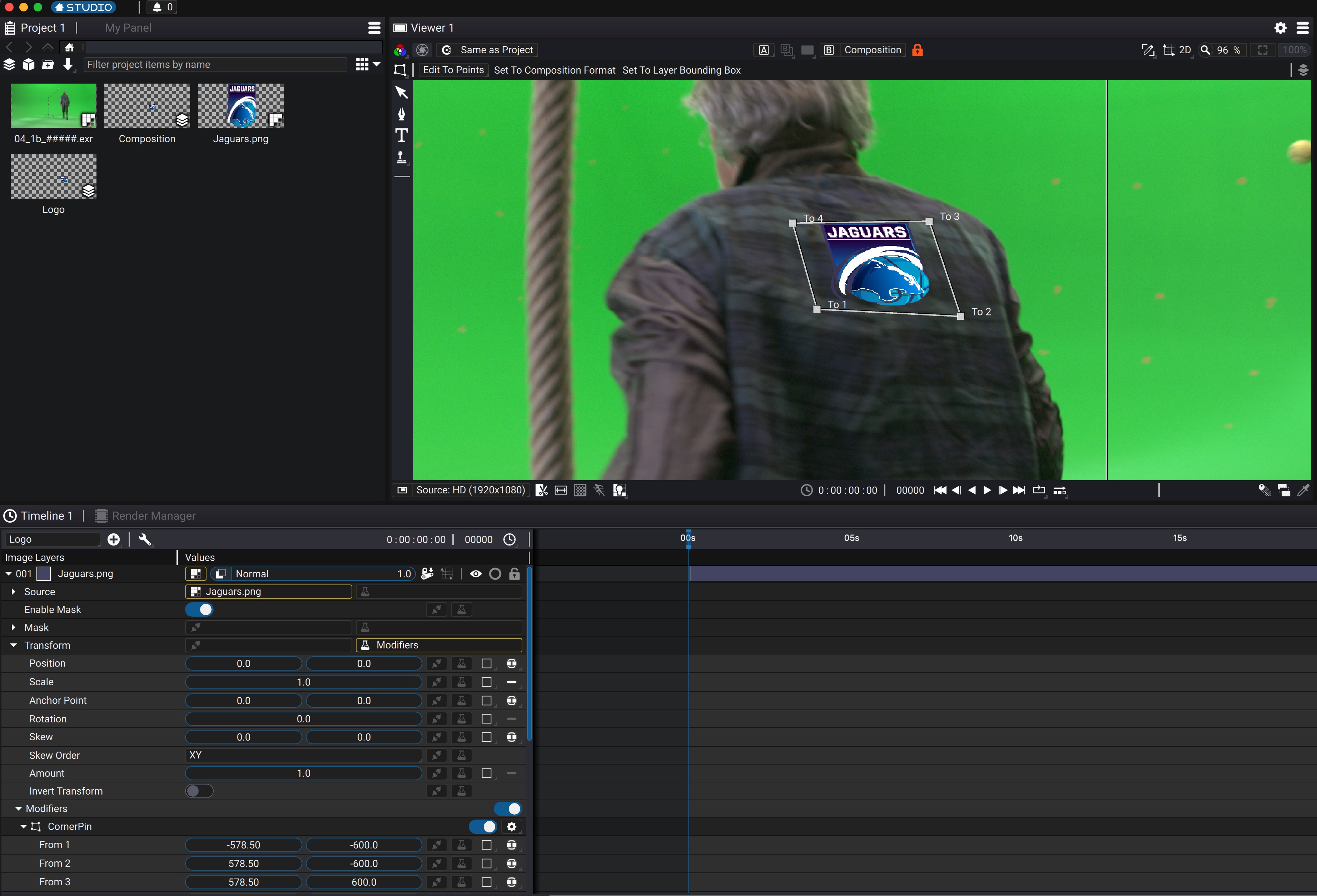
In the above example, the Logo Composition contains the logo layer, on which a CornerPin has been set as modifier of the Transform. In order to be able to move the CornerPin in the context of the final render, the viewer is locked on the main Composition.
Once the setup is correct at the reference frame, just playback or scrub the timeline to see the image being match-moved.
If the logo starts to drift or turns into a soup, you may have to use the more advanced Vector Corner Pin modifier which allows you to set keyframes to prevent drift.
Controls
| Parameter / Script Name | Type | Default | Function |
|---|---|---|---|
Enabled / enabled | Boolean | On | |
Reference Frame / referenceFrame | Time | 0 | The frame at which the generated UV-Map will be identity, that is, will not produce any deformation. This should be the frame where the region you want to match-move is clearly visible. Changing this requires recomputing the UV-Map sequence. |
Frame-Range Mode / frameRangeMode | Choice | Layer Range | Specifies the frame-range to use when generating UV-Maps - Layer Range - Custom |
Start Frame / firstFrame | Time | 0 | The first frame at which to generate UV-Map |
End Frame / endFrame | Time | 1 | One frame past the last frame at which to generate UV-Map, that is, if you want to generate only 1 frame, this value should be Start Frame + 1 |
Generate UV-Maps / launchTracking | Button | Off | Launch the generation of UV-Maps |
Motion Estimation / motionEstimation | Category | - | |
Motion Source / motionSource | Image | - | The footage that will be used to compute the motion-vectors |
Track Region / roi | -200, -200, 200, 200 | Only pixels within this region will be tracked. This is useful for example if you need to track a small portion of the image. Note that the rectangle should be large enough to enclose all possible position of the pixels throughout the track length | |
Track Region Mode / roiMode | Choice | Whole Image | The region used to track the pixels. Selecting Track Region and defining a smaller rectangle may improve performances - Track Region - Whole Image |
EXR Disk Cache Path / cache_path | File | Path where computed motion vectors and UVMaps are stored. The ${ProjectDir} variable can be used to refer to the directory where the project file is located. If the project is not yet saved, the vectors are stored in a temporary location on your system | |
Filename Identifier / uv_basename | UV-maps and motion vectors files will be named on disk as following with: "uv_" or "mv_", followed by this identifier and ending with informations such as frame distance, reference frame and frame numbering | ||
Frame Distance / frame_distance | Float | 1 | Number of separating frames between a frame and the next when computing motion vectors. A higher value will smooth out jitter. It affects the tracking of motion-vectors and UV-Maps |
Use GPU If Available / use_gpu | Boolean | Off | Use CUDA for motion-vectors computation if possible. Results may differ slightly from CPU version and depending on the CUDA driver. It is safer to leave it disabled. |
UV-Map Blur / blur | Float | 0 | Smooth the UV-Map as a post-process before applying the UVs. It does not affect the tracking process |
Track Red / track_red | Boolean | On | Consider the source image red channel when tracking |
Track Green / track_green | Boolean | On | Consider the source image green channel when tracking |
Track Blue / track_blue | Boolean | On | Consider the source image blue channel when tracking |
Algorithm / of_algo | Choice | Dense Inverse Search | - Dense Inverse Search - Dual TV L1 |
Finest Scale / of_dis_finest_scale | Float | 1 | The finest level of the Gaussian pyramid on which the flow is computed (zero level corresponds to the original image resolution). The final flow is obtained by bilinear upscaling. |
Patch Size / of_dis_patch_size | Float | 8 | Size of an image patch for matching (in pixels). Normally, default 8x8 patches work well enough in most cases. |
Patch Stride / of_dis_patch_stride | Float | 3 | Stride between neighbor patches. Must be less than patch size. Lower values correspond to higher flow quality. |
Descent Num. Iterations / of_dis_gradient_descent_iters | Float | 25 | Maximum number of gradient descent iterations in the patch inverse search stage. Higher values may improve quality in some cases. |
Refinement Num. Iterations / of_dis_var_refinement_iters | Float | 5 | Number of fixed point iterations of variational refinement per scale. Set to zero to disable variational refinement completely. Higher values will typically result in more smooth and high-quality flow. |
Refinement Smoothness Weight / of_dis_var_refinement_alpha | Float | 20 | Weight of the smoothness term |
Refinement Gradient Constancy / of_dis_var_refinement_gamma | Float | 10 | Weight of the gradient constancy term |
Refinement Color Constancy / of_dis_var_refinement_delta | Float | 5 | Weight of the color constancy term |
Robust To Illumination Changes / of_dis_use_mean_propagation | Boolean | On | Whether to use mean-normalization of patches when computing patch distance. It is turned on by default as it typically provides a noticeable quality boost because of increased robustness to illumination variations. Turn it off if you are certain that your sequence doesn't contain any changes in illumination. |
Spatial Propagation / of_dis_use_spatial_propagation | Boolean | On | Whether to use spatial propagation of good optical flow vectors. This option is turned on by default, as it tends to work better on average and can sometimes help recover from major errors introduced by the coarse-to-fine scheme employed. Turning this option off can make the output flow field a bit smoother |
Time Step (Tau) / of_dualtvl1_tau | Float | 0.25 | Time step of the numerical scheme |
Attachment Weight / of_dualtvl1_lambda | Float | 0.15 | Weight parameter for the data term, attachment parameter. This is the most relevant parameter, which determines the smoothness of the output. The smaller this parameter is, the smoother the solutions we obtain. It depends on the range of motions of the images, so its value should be adapted to each image sequence. |
Tightness Weight / of_dualtvl1_theta | Float | 0.15 | Link between the attachment and the regularization terms. In theory, it should have a small value in order to maintain both parts in correspondence. The method is stable for a large range of values of this parameter. |
Pyramide Size / of_dualtvl1_nscales | Float | 5 | Number of scales used to create the pyramid of images |
Num. Warps / of_dualtvl1_warps | Float | 5 | Number of warpings per scale. This ensures the stability of the method. The higher it is, the more accurate it is, but slower |
Error Tolerance / of_dualtvl1_epsilon | Float | 0.01 | Stopping criterion threshold used in the numerical scheme, which is a trade-off between precision and running time. A small value will yield more accurate solutions at the expense of a slower convergence. |
Inner Iterations / of_dualtvl1_inner_iter | Float | 30 | Iterations number used when filtering outliers |
Outer Iterations / of_dualtvl1_outter_iter | Float | 10 | Number of iterations used in the numerical scheme |
Scale Step / of_dualtvl1_scale_step | Float | 0.8 | Step between pyramid scales |
Median Filter Size / of_dualtvl1_median_filter_size | Float | 5 | Size of the median filter kernel (1 = no filter). Must be 1, 3 or 5 |
Render Settings / uvmapParams | Category | - | |
Red / process_red | Boolean | On | Enable the red channel in output. Otherwise if there's a source the content of the main source is returned instead, else 0 |
Green / process_green | Boolean | On | Enable the green channel in output. Otherwise if there's a source the content of the main source is returned instead, else 0 |
Blue / process_blue | Boolean | On | Enable the blue channel in output. Otherwise if there's a source the content of the main source is returned instead, else 0 |
Alpha / process_alpha | Boolean | On | Enable the alpha channel in output. Otherwise if there's a source the content of the main source is returned instead, else 0 |
Scale / scale | Float 2D | 1, 1 | A scale factor applied to the uv value at each pixel of the uv map |
Offset / offset | Float 2D | 0, 0 | An offset subtracted from the u value at each pixel of the uv map. This is applied after scale |
Wrap U / u_wrap | Choice | Black | How the source image is accessed when the X coordinate is out of bounds - Black - Clamp to edge - Repeat - Mirror |
Wrap V / v_wrap | Choice | Black | How the source image is accessed when the Y coordinate is out of bounds - Black - Clamp to edge - Repeat - Mirror |
Supersampling / supersampling | Choice | x1 | The supersampling factor. Higher means more quality and antialiasing but slower to render - x1 - x2 - x4 - x8 - x16 |
Filter / filter | Choice | Inherit | The antialiasing algorithm used as reconstruction filter. Note that if the uv map contains offset where 2 source pixels do not end up close-by in the output image, any reconstruction filter would produce incorrect results by mixing pixels that are apart in the source image. The only correct way to antialias in this mode is using a supersampling factor below and set filter to Nearest - Inherit: Inherit parent layer filter - None: No interpolation - Box: Box filter - Triangle: Bilinear filter - Hermite: Hermite interpolation filter (smoothstep in glsl) - Hann - Hamming - Blackman - Gaussian - Quadratic - Cubic: General Cubic Filter. Emulates a Gaussian Blurring Filter. This curve is also known as a 'B-Spline' interpolation curve, and is also commonly used for drawing smooth lines through a collection of points. It is also often used for camera and object motions in animations, to produce a smooth flow though the user provided control point - Spline 16 - Spline 36 - Spline 64 - Spline 100 - Spline 144 - Catmull-Rom - Mitchell - Keys - Keys Sharp - Sinc - Jinc - Kaiser - Welch - Parzen - Bohman - Cosine - Bartlett - Lagrange 3 - Lanczos 2 - Lanczos 2 Sharp - Lanczos 3 - Lanczos 3 Sharp - Lanczos 4 - Lanczos 6 |
Mask / mask | Image | - | |
Mix / mix_with_source | Float | 1 | Dissolves between the original image at 0 and the image with the effect applied at 1 |